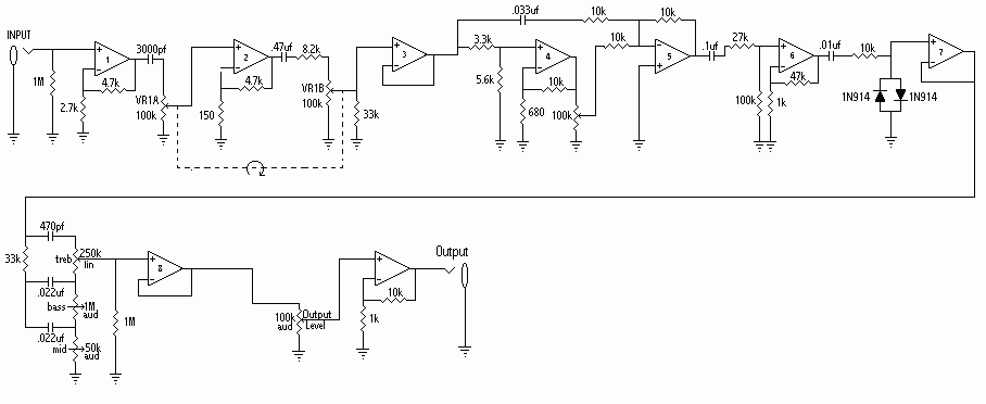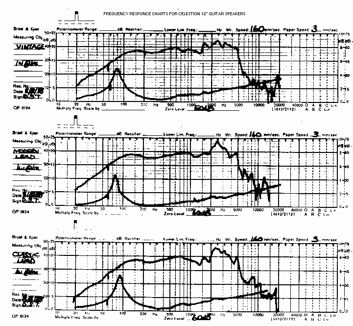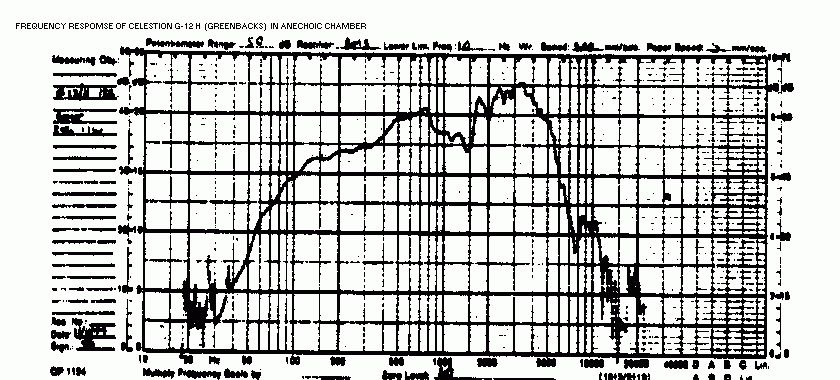
LXH2 "Marshall" Simulating Preamp Schematic
Includes both preamp and speaker/cabinet simulator sections.
!!!!! IMPORTANT WARNING !!!!!
Do NOT connect this circuit to the speaker output jack on your amp. Serious damage can
occur to both your amp and this circuit and can cause a fire hazard. This is a line level
device. Use only with preamps, effects processors, and other line level equiptment. Line
level refers to the output level of most mixers, preamps, and effects processors.
FILTER DATA TABLE:
Notes:
1. Connect all [peaks] MFB filters together in paralell where shown.
2. Connect all [dips] MFB filters together in paralell where shown.
3. Keep all leads as short as possible to prevent oscillations.
4. All power supply connections are not shown in this drawing.
MFB FILTERS FOR PEAKS
In all MFB filters below, C represents C1 and C2.
MFB FILTER 320 HZ 800 HZ
1.2 KHZ 1.8 KHZ
2.5 KHZ
R1
270k
270k
180k
120k
330k
R2
4.3k
3.0k
2.2k
1.2k
5.1k
R3
110k
150k
82k
68k
180k
R4
12k
12k
12k
12k
11k
C
.022uF
.01uF .01uF
.01uF
.0022uF
MFB FILTER 5 KHZ 8 KHZ
11 KHZ
R1
247k
390k
68k
R2
5.4k
4.4k
1.15k
R3
202k
270k
570k
R4
18k
16k
15k
C
.001uF
560pF 560pF
MFB FILTERS FOR DIPS
MFB FILTER 600 HZ 1.45 KHZ
2 KHZ 7 KHZ 9 KHZ
R1
220k
120k
330k
220k
56k
R2
6.8k
1.2k
1.5k
9k
8.2k
R3
120k
100k
180k
202k
39k
R4
11k
10k
22k
10k
5.6k
C
.01uF
.01uF
.0047uF 560pF
.001uF
TECHNICAL NOTES:
1. All op-amps are TLO84.
2. The "cabinet" and "damping" circuitry in the lower
portion of this schematic provides an adjustable resonant boost around 100 Hz for use with
guitar speakers powered by high damping factor solid state amps. The total low frequency
response is more like the resonant response of a sealed 4-12" guitar cabinet powered
by a low damping factor amp such as a distorting tube amp.
3. For best results, all potentiometers should be audio taper except the
250K treble control which should be linear. For best results, the 10k "damping"
control should be audio taper, using the "low" and wiper leads (left two leads
if you view the front of the pot with the leads pointing down). This makes the resistance
increase more slowly as you increase it, for best taper in damping. Counterclockwise
rotation decreases damping (increases bass resonance). Otherwise, make this potentiometer
linear.


Copyright (C) 1997, 1998 LXH2.