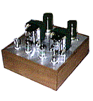
A Zero-Feedback SSRP-Input Headphone Amplifier
by Simon Busbridge

I recently purchased the Sennheiser HD600 headphones second-hand and realised that their full potential could only be met with the highest quality amplifier. Hence this project! Before starting there were certain criteria I wanted to satisfy:
Output transformerless designs either use direct coupling or capacitor coupling. In the former case the possibility of DC appearing at the output is very real, either at switch on or when plugging the 'phones in and out (when the common connection in the plug can short the right channel jack output). With capacitor coupling it is usual to use a delayed muting switch to prevent switch on and off "thumps". Generally speaking, there are no turn on and off thumps on transformer-coupled amps because the current in the output valve tends to build up and decay slowly, a fade-in and fade-away type of effect. Muting circuits on other designs are fine, but a transformer does offer the ultimate in terms of protection (damage to the headphones and electric shock).
So that really decided the form of the output - it had to a transformer. To get a low output impedance I needed to use quite a high step-down ratio; after all, the amplifier may be used with headphones of lower impedance that the 300 Ohms of the HD600. For T1, I used 20:1 line output transformers (part no. pa106 from SJS Electroacoustics). The output valve is the 12B4A which has a anode impedance of about 1000 Ohms, so the output impedance of the amplifier is about 2.5 Ohms, which is very low for a valve amplifier. You can use other valves here but watch that the anode impedance is not too high or the output impedance and bass-cut off frequency will both rise.
It is usual with power amplifiers to match the impedance of the loudspeaker to the impedance of the anode circuit using the equation turns ratio = square root (impedance ratio). Under these conditions, maximum power transfer takes place from the amplifier to the load. With headphones, the power involved is so small that it is not necessary to operate under such conditions. It is possible to make the turns ratio such that the output impedance of the amplifier is much smaller than the load. Power transfer is not optimum, but the output valve is tending to run under constant current conditions which has the advantage of lowering distortion.
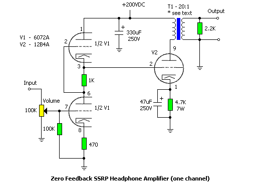
Figure 1
The output power will depend on the impedance of the headphones; the amp gives about 10 V output before clipping. The gain of the output stage is 0.33, so quite a bit of amplification is needed before it. I am a fan of SRPP because it improves linearity, lowers output impedance and allows for a large voltage swing. The first stage uses a double triode directly coupled to the output valve, giving an overall gain of about 20 dB. The circuit is shown in figure 1. The 12B4A cathode resistor tends to run quite hot so use a 7 W component here.
There is no feedback from the output to the input. The gain can be increased slightly by decoupling the cathode of the SRPP input, or alternatively try a ni-cad battery bias. Although I use the 6072A for this stage, suitable alternatives are the 5965 and 12AT7. The 12AT7 is slightly less linear. The 6922 can also be used with a change to the heater wiring but the gain will be lower.
The 2.2 K Ohms resistor on the output of the audio transformers is there to give the output valve some load if the headphones are disconnected. Without it, the transformer can ring off load. The output impedance of the amp is so low that its value is quite uncritical. I have only given the power rating of resistors which dissipate any appreciable power. For all others, 0.5 W resistors will do.
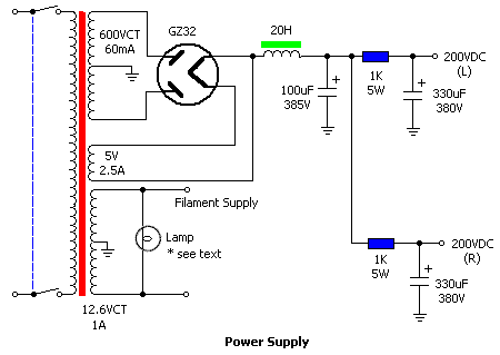
Figure 2
The power supply, shown in figure 3, is fairly conventional, with valve rectifier and choke input filter for quiet operation. An extra stage of filtering removes any residual ripple and helps to separate the channels. All sorts of different power supplies can be used, but it needs to be capable of 60 mA at 200V. The 200V HT voltage is not critical. DC can be used on the heaters, but it is not really necessary as the gain is fairly low. The transformer and choke were custom-made by Sowter of Ipswich. I paid 165.59 UKP for the two.
Solid state power supplies can be used. They just don't sound as good!
The lamp is an integral diode, resistor and led in a chrome mounting. You might wish to consider fitting a fuse at the input. In the UK all plugs are fused and I tend to use this for protection but continental Europe and USA plugs may not have this facility.
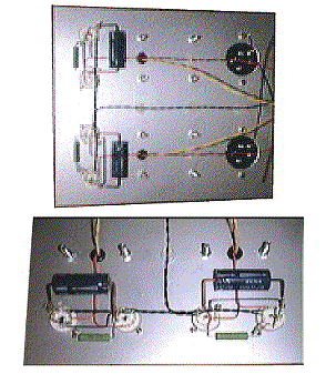
Figure 3
The complete system is built on two separate chassis to avoid magnetic field induced hum (I recommend that you ask for a flux-band and earth-screen to be fitted to your transformer). If it is kept on two chasses (amp on one, psu on the other), then component placement is quite uncritical. For ease of assembly, I tend to use 1.6 mm sheet metal for the chassis top (reinforced with square cross-members near the transformers) recessed into a wooded frame assembled from mitered components. The wooden parts can be spray painted black and then polished for good effect. The finish is excellent as the grain of the wood shows through.
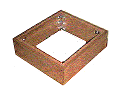
Figure 4
The input phono jacks are located round the back, along with the unbilical between power supply unit and the amplifier. When the chassis is complete, the headphone jack will be on the front (left) next to the volume control (right). I am waiting for a sample of a gold plated special socket from Switchcraft, but as they are out of stock I haven't drilled the holes yet.
The sound quality of the amplifier is excellent. The lack of feedback produces an open natural, detailed, sound without any of the harshness sometimes experienced with solid state amplifiers. I can now listen in bliss well into the night when other members of the household have gone to sleep! This is definitely one of my best projects.
Addendum
6/7/99: Added paragraph discussing output transformer impedance when driving headphones.
c. 1999, Simon Busbridge.