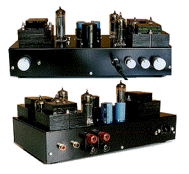
A SSRP-Input Amplifier For Headphones and Loudspeakers
by Tony Frazer

I built the prototype of this headphone amplifier in Oct'96 and remain impressed by it's
performance. Imaging is particularly good - I make much greater use of my headphones than
ever before! Hum is low and unintrusive. I have used 60 ohm and 300 ohm headphones with
this amp. The amp is designed also to drive an efficient pair of 8 ohm loudspeakers. If
you do build it, please let me know how you get on - ideas for improvement are always
welcome!
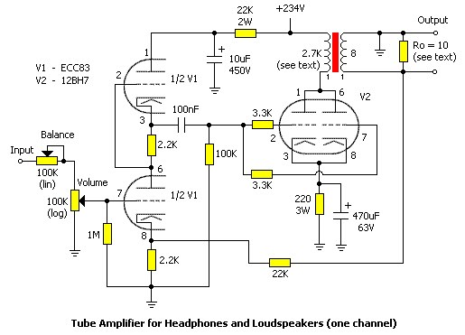
Figure 1
Figure 1 shows the amplifier schematic for one channel. The circuit topology is a SRPP (Series Regulated Push-Pull) input stage which is AC-coupled to a Parallel-Triode Cathode Bias output stage. To check the circuit gain, I injected a 1kHz sine wave at 1V p/p into the grid of the lower V1. I measured 12V p/p at the grid of V2, and 110V p/p at the anode of V2. The output stage runs at 32mA, 234V, i.e. 7.5 Watts. Class A amplifiers are typically about 20% efficient, so it would be reasonable to expect about 1.5 Watts output.
The amp was designed to work with 8 ohm loudspeakers. Nearly all loudspeaker drive units I have encountered have a nominal impedance of 8 ohms - of course this varies with frequency by a few ohms. When driving headphones, the audio output transformer must be shunted with a 10-ohm resistor (Ro) to present the correct load to the transformer secondary. The shunt allows higher impedance headphones to be used. Remove the shunt (add a switch to take it out of the circuit) when driving loudspeakers.
A wide range of headphone impedances can be used with this amplifier because of its low impedance output. A pair of 60 ohm headphones will present 1/((1/10)+(1/60))= 8.57 ohm load with 60 ohm headphones, while the amp will see a 1/((1/10+(1/300)) = 9.68 ohm load with 300 ohm headphones. I know it isn't efficient from a dedicated headphone amplifier perspective, where the output transformer would have a secondary matched to the headphone impedance. However, with the 10-ohm shunt, there is still plenty of power.
CONSTRUCTION NOTES
WARNING: Tube circuits involve potentially LETHAL HIGH VOLTAGES and should only be tackled by experienced persons with due regard for SAFETY. Don't fiddle with the circuit while wearing your 'phones!
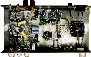
Figure 2
General construction notes for my prototype:
The unit is built on a two-section 'U'-type Aluminium chassis WxDxH:12x6x2" with holes in the base section and around valveholders for ventilation.
Chassis plate layout:

+-------------------------------+  Key:

|         [h] [h]  [V2] [o/p ]  |  tr = Mains Transformer

|[   ]    [c] [c]       [    ]  |  R = rectifier tube

|[tr ][R]              [V1][V1] |  h = heater supply capacitor

|[   ]      [C]         [    ]  |  c = 100uF HT capacitor

|                  [V2] [o/p ]  |  C = 330uF HT capacitor

+-------------------------------+  V1 = 7025; V2 = 12BH7

                                   o/p = SE output transformer
AMPLIFIER CIRCUIT NOTES:
Stock Number / Description
YJ61R / 20VA Transformer Kit
YJ62S / 50VA Transformer Kit
Maplin Electronics also do copper wire on 50g and 250g reels in the gauges required (I
would suggest the 250g reels). Heavy items such as transformers have an additional
carriage charge.
Maplin Electronics
PO Box 777
Rayleigh
Essex SS6 8LU
United Kingdom
Laminations 2 5/8" x 2 1/4"; 7/8" stack. I use a variable-speed hand drill and a coach-bolt/wooden block which the bobbin fits over. On slowest speed, I count revolutions for a minute, then calculate winding time from that. Secondary is wound manually. Don't interleave 'E' and 'I' laminatons as you would with a power transformer. No extra gap spacer is required as the ampere turns are well within limits for DC saturation. I use plenty of 1-hour epoxy resin to hold it all together. (That was not intended to be a lesson in winding transformers!)
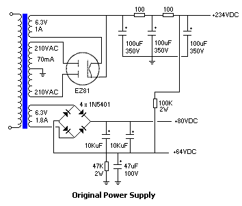
Figure 3
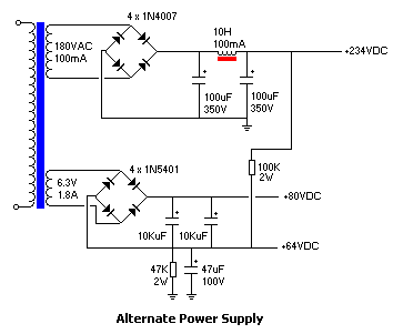
Figure 4
NOTES ON THE POWER SUPPLY:
There are two versions of the power supply: the original prototype's power supply (figure 3) and an all-silicon version (figure 4). The original uses a half-wave thermionic rectifier (EZ81). The all-silicon power supply uses a different transformer HT secondary, and the rectifier heater winding is not required. I have shown a capacitor-choke-capacitor filter which should prove quieter than the original resistor-capacitor chain filter.
Basically, the PSU provides +234V DC for the amp and 6.3V DC for the heaters, but because I am using an SRPP stage where the cathode of the upper half of V1 is at quite a high voltage with respect to gnd, I use the voltage-divider network to 'pull up' the heater voltage (with respect to gnd) to reduce the potential difference between cathodes and heaters.
Some tubes have a specified design limit - I got into the habit of doing this with SRPP stages using the 6072 tube for which a maximum of 90 volts K/h is specified, however the ECC83/12AX7 has a maximum 'peak' K/h of 200 volts specified - it is arguably unnecesary for the ECC83, but for the cost of a couple of resistors and a cap. it seems a worthwhile precaution to prolong tube life, or when experimenting with different tubes.
A green L.E.D. and 1K5 resistor (not shown) are connected across the smoothed heater supply as a pilot light.
Addendum
11/9/98: Corrected resistor value from 47 to 47K ohms in figures 4 and 5.
c. 1997, Tony Frazer.
Republished with permission.