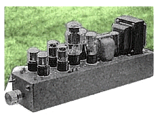
Brute Force In A Line Stage
by Eric Barbour

The need for a high-gain stereo preamp has diminished, because the CD has replaced the LP record in most audiophile homes. Most CD players produce enough voltage to drive nearly all amplifiers directly to full power, so you require only a volume control, or a switch if there is more than one source signal, as from an FM tuner. Also, you need a line stage preamp if there isn't enough output voltage from one of the sources. The CD may have rid us of the preamplifier as a necessity, but not all line-level sources are compatible, and some gain may be required.
Another, often forgotten, purpose of the preamp is to drive your headphones. Although most of today's "audiophile" preamps lack a headphone jack, the solid-state ones could adequately drive phones. Tube preamps are another matter. A semiconductor driver usually feeds the low-impedance load, as with the Melos SHA-1. Its tubes drive a MOSFET output. Sometimes, especially late at night, I listen through headphones with a pair of AKG K240s (600 ohms), which is a relatively easy load to drive. But I wanted to design an all-tube line stage and driver that could power them, without resorting to output transformers
Design Criteria
My design philosophy was to achieve "purity." My experience with the common weaknesses of existing preamps helped me determine the following basic rules for designing a "pure" line stage:
1. All tube, no semiconductors if possible;
2. No electrolytic capacitors, if possible;
3. Best possible insulation materials;
4. Best possible tube types without resorting to rarities;
5. Regulated power supply;
6. Low output impedance without iron to drive 600 load;
7. Sufficient voltage gain of 10-20;
8. No feedback, stable, minimalistic.
Experimentation
I have many opportunities to experiment with other equipment. I have tried innumerable preamps based on 12AX7 and 6DJ8 types, including Dynaco PAS-3s with every modification imaginable; McIntosh C11, C20, and C22; Scott 130; various Audio Research units; old NYAL Minuets; Lafayette KT-600 (probably the best of the vintage units); and some home-brews.
Not one of them had the real magic. In my opinion, most 12AX7s have a "lumpy" sound and do not maintain similar frequency response between channels, because negative feedback tends to "amplify" response aberrations, especially when tubes age and drift. The 6DJ8s have a wiry, irritating sound to me. I believe that some listeners confuse this kind of distortion with extreme sonic detail.
Although probably the best of the manufactured preamps, the old MFA Luminescence (currently out of production) isn't perfect. It is too complex, the phono stage is a bit of a monstrosity, and the line stage uses unnecessary negative feedback. It uses all octal-based tubes, which tend to produce better sound than similar miniature types. Maybe octals have a less microphonic character, but of a more pleasing type.
Two of my acquaintances, who each have a Luminescence, both complain about the unit running too hot to touch. And the line stages drift, so they often must look for closely matched 6DN7s. Also, the 7591 in the power supply and all the 5691s in the phono stage add to the expense of keeping this unit running. (As a substitute for the 5691s, Luminescence owners could try 6SL7s, which work just as well and at a fraction of the price.)
I believe octal tubes are the best choice. It is difficult to beat a good 6SN7 for audible excellence at a low price. You can use other tubes, but for both present and future availability, the SN is tops. It's like an old friend who doesn't let you down. Even the Russian versions sound better to me than any 12AU7.
Circuitry
A cathode follower based on the 6BL7 or 6BX7 is ideal for output. I used a mu-follower circuit with no feedback, a 12SN7 as the gain stage, and a 6BL7 as the cathode follower/current source. (I have many old GEs I wanted to use, and converting to 6SN7 means simply changing the hookup to the 24V filament transformer). You might argue that the current source should be a pentode of highest possible gain, but pentodes can be noisy, and one of my design goals was minimalism.
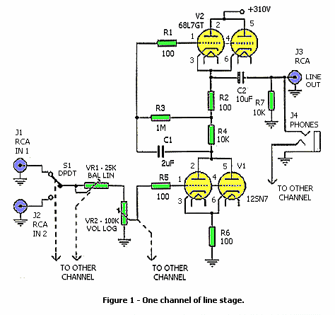
The line stage (Fig. 1) is a straightforward mu follower, with medium-mu triode 12SN7GT below and low-mu triode 6BL7GT above. I paralleled both sides of each tube for maximum lifetime and for minimum output impedance. I chose resistors from my junk box, so there is nothing sacred about the values shown.
The 10F capacitor on the output was calculated to give a -3dB low-frequency cutoff of 26.5Hz when working into a 600 load. You can build all the circuitry point-to-point on ceramic terminal strips of the type from old "junker" Tektronix tube oscilloscopes (mine were surplus NOS) or from Triode Electronics. All the sockets are premium ceramic octals with silver contacts. You probably don't need DC for the filaments, because the filament wiring is run inside grounded copper shield braid right up to the sockets.
This circuit should work fine with a 6J5, 12SX7, 6CG7, or 12AU7 as the lower tube, and a 6BX7, 12B4, or triode-connected 6BQ5 as the upper tube. Any of the miniature TV dual triodes such as 6DE7 or 6EW7 can serve as both top and bottom triodes since they contain a medium-mu and a low-mu section. (This wouldn't be my choice, since the octals seem to sound better, but you may choose the tubes you like.)
I rescued a four-section Alps volume control from a scrapped Kenwood amp as a potentiometer. It is very similar to the Old Colony unit. The center shaft is volume, and the outer ring is a balance trimmer. I provided two stereo inputs, selected with a DPDT switch. All the RCA jacks are on top of the chassis, very close to the audio circuits to allow for minimum path lengths and easier cable hook-up (I hate reaching around behind components to mess with interconnects). Heat from the tubes is not the problem you might think; I laid a cable on top of a 6BL7 for eight hours (they run hot), and the insulation didn't soften.
Power Supply
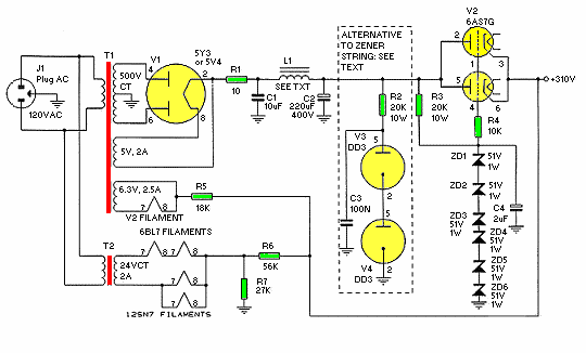
The power supply (Fig. 2) is regulated, has slow warmup inherent in its operation, and is simply designed. I chose the 6AS7G for looks; it's much bigger and lights up more impressively than a 6080. The only problem was with the voltage standard. As I've stated before in GA, gas tubes are capable of impressive noisemaking.
Also for appearances, I installed two OD3s, but was never able to clean them up enough for optimal results. There was always at least 10mV of hash on the 6AS7 output, even when I selected the quietest among 40-plus OD3s and added all kinds of LC iltering. They also have a charming tendency to oscillate at audio frequencies as they age. So I left them hooked up to the raw power supply (they look impressive with their purple glow) and used a string of 51V zeners on the 6AS7 grids. So much for "purity."
The 5Y3 rectifier is an old classic still in production, but a 5V4 will also work here without changing any wiring. The power transformer is a "radio replacement" type surplus unit I bought many years ago. It must have been more than 30 years old, as the original $5.88 retail sticker was still on it. Its regulation is not very good, without an electronic regulator and LC filter. I used a 10F Sprague 735P as a supply filter simply because I had some surplus units, which fit into the narrow chassis. There is only one electrolytic in the whole preamp; C2 had to be changed from a film type to minimize hum.
You do not need a vast filter capacitor with this circuit; the AC ripple on the 6AS7 plate is less than 10mV. The choke is an old 20H Triad unit, probably military surplus. If you can't find one, try two conventional 10H units in series. R1 is simply a small 10 resistor serving as a safety fuse.
This supply is good, with no-load to 50mA regulation of about 5V DC. With both stages putting out 91V P-P sine wave into a 100k load, I put an oscilloscope on the regulated 310V supply line and observed less than 20mV P-P of audio signal.
Rave Review
As it turned out, with my AKG headphones plugged into the output jack, the -3dB cutoff was below 20Hz. Plate current of this stage is about 25mA with 310V plate power. Gain is about 17.4 and seems very stable. After a few months of regular use, it hasn't decreased substantially. With the AKG headphones as a test load, frequency response was from below 20Hz up to 86.4kHz.
There is plenty of headroom: I measured 91.2V peak-to-peak before the onset of clipping (with a 100k high-Z load on the output). This is an excellent circuit to use in a single-ended 300B amp as the driver stage. IM distortion was 0.03% with 1V P-P into the 600 load. I measured an output impedance of about 300 with the 600 phones plugged in, which could be decreased by bypassing the cathode resistors (R6) with a large capacitor of 1,000F or more at 25V. This wasn't necessary because by the time the phones cause audible load distortion, they are unbearably loud.
Purity Attained
The resulting sound was excellent. Used as a line stage, this design is virtually immune to the bizarre "tweak" cables that plague audio today. I tried a few borrowed types, from preamp output to power amp input, and there was no noticeable difference in sound quality. As a headphone driver, it produces excellent space and detail without the harsh transistor quality of other headphone drivers, and is genuinely euphonic and accurate at the same time.
TABLE 1
PARTS LIST
For each line stage channel:
R1,R5 100 1/4W carbon
R2,R6 100 1W metal film
R3 1M 1/4W metal film
R4 10k 25W wirewound
R7 10k 1/2W metal film
VR1,VR2 Part of Alps quad volume/balance control
C1 2F 400V polypropylene
C2 10F 400V polypropylene
V1 12SN7GT (GE) or 6SN7GT (see text)
V2 6BL7GT (GE)
For power supply:
R1 10 1/2W metal film
R2,R3 20k 10W wirewound
R4 10k 1/4W metal film
R5 18k 1/2W metal film
R6 56k 2W metal film
R7 27k 2W metal film
C1 10F 400V polyprop
C2 220F 400V electrolytic
C3 0.1F 400V Mylar
C4 2F 400V polyprop
T1 power transformer, 250-0-250V 50mA, Thordarson 24R09 or similar
T2 filament transformer, 24V CT 2A, Mouser 41LK020 or similar
L1 choke, 20H 50mA, two Triad C-3X in series (see text)
Other: (8) ceramic octal sockets, (5) 7-position ceramic terminal strips, (6) chassis-mount RCA sockets, aluminum chassis 15" 4" 3", AC power cord with strain relief, knobs for pot, DPDT miniature switch, Teflon-insulated wire, 1/4" copper tubular braid, stereo 1/4" panel-mount phone socket, assorted hardware.
Addendum
10/7/98: Changes to power supply schematic (figure 2): R1 restored. Also an EL34 with a 100 ohm resistor connecting the plate to the screen can substitute for the 6AS7.
Options for the amplifier: A 6AG7 can work in place of the 6BL7 and 1/2 of a 6SL7 for the lower tube. Set R4 = 68K and R5 = 820 ohms as a shunt regulator for the 6AG7 screen.
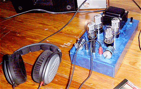
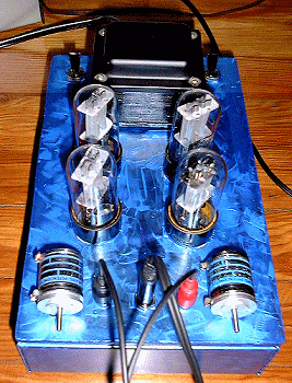
7/15/00: Eduard Orvisky built this headphone amplifier using ideas from Kurt Strain's and Eric Barbour's designs. It uses two 6SN7s in the mu follower (R2 is reduced to 2K, 2W), and solid state and rectified heaters (he also tried a 5Y3 tube rectified supply, but preferred the solid state version for its faster sound). More details of this design can be found on his website.
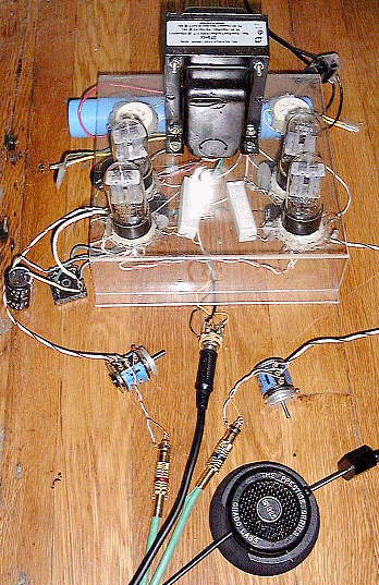
9/1/00: Eduard Orvisky gave his amp to a new chassis and gave it a stunning paint job. He writes: "I sprayed it matte black in the beginning, but did not like it. Did not look bad, but it was too obvious. Then I tryed silver metallic. That was worse, not as real polished metal. Then I painted acrylic sapphire blue on it. With brush, hence the strokes."
Eric Barbour is an applications engineer with Svetlana Electron Devices and holds a BSEE degree from Northern Arizona University. He has been a staff editor with VACUUM TUBE VALLEY magazine since its founding in 1995, and has been a regular contributor to GLASS AUDIO magazine since 1991.
c. 1995, Audio
Amateur Publications, Inc., P.O. Box 576, Peterborough, NH 03458, USA. All rights
reserved.
From Glass Audio, Issue
4/1995, pp. 1, 6, 8, 10. (Republished with permission.)