Not Just Another Headphone Amp
by Alan Gary Campbell
The ping of the cymbals, crack of the snare drum, thonk of the bass - none of these comes through on my low-budget speakers. Sometimes they sound so fuzzy I want to hide behind the couch until its over. But headphones...ah, heaven!
There are probably as many headphone amp designs as there are headphones, but all arent created equal. The cheesy headphone-amp circuits in most stereo gear arent up to the standards of the main amp components, and many CD players and cassette decks dont even have them.
This do-it-yourself stereo headphone amp sounds clean and clear, and uses just two, inexpensive chips. Its great for practice, multitrack monitoring, or just plain listening as a receiver/integrated-amp substitute.
THE CIRCUIT
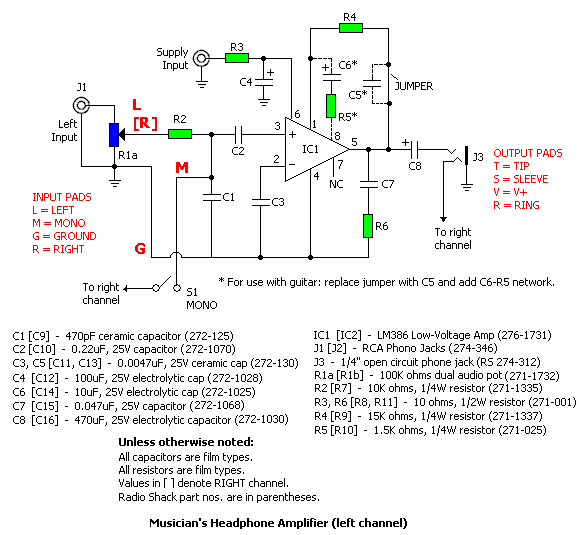
Figure 1
The circuit gets its zip from two National Semiconductor LM386 Low Voltage Audio Power Amp ICs, one for each side of the stereo path. The left and right channels are identical. Refer to the schematic, Fig. 1, using the left channel as a guide. Dual potentiometer R1A serves as variable input-attenuator (the dual pot controls both channels); R2 isolates C2, which capacitively couples the input. Cl bypasses high-frequency input noise to ground; C3 bypasses the inverting input. R3 and C4 bypass the power supply. R6 and C7 bypass the output; C8 capacitively couples it.
The LM386 is internally configured to provide a gain of 26 dB: this is a bit too much for line-level inputs. R4 reduces the gain by -6 dB. If you want to tailor the response for guitar signal input, you will have to add some additional components (indicated with dotted lines), because the guitar output is a low-voltage signal with a predominance of high frequencies. C5 (which substitutes for the indicated jumper) rolls off the high frequencies at -6 dB/octave, with a cutoff frequency of about 5kHz. R5 and C6 provide about +6dB of gain recovery to boost the signal.
BUILDING IT
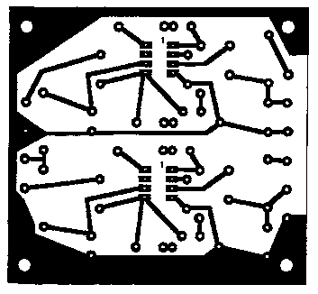
Figure 2 - PC Board Pattern.
The sound quality youll get from your headphone amp will be directly proportional to the quality of the passive components it incorporates. Use the best poly and low-leakage electrolytic capacitors you can obtain. Metal-film resistors help maximize the signal-to-noise ratio, though Ive had good results with carbon-film types.
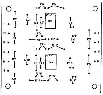
Figure 3 - Parts Layout.
Perf-board construction is fine. If you want to make your own PC board, Fig. 2 shows a full-size, 1:1 pattern, and Fig. 3 shows the parts layout. If you intend to use the headphone amp solely with guitar, add the optional components indicated with the dotted lines (C5. R5, C6, C13, R10, C14, and the mono switch). Pads are provided on the PC layout. For line-level applications (synth, tape, CD, etc.), omit these components and install jumpers across the C5 and C13 locations, as indicated. Note that guitars feeding effects, active guitar pickups. and even some passive pickups are hot enough to drive line inputs.
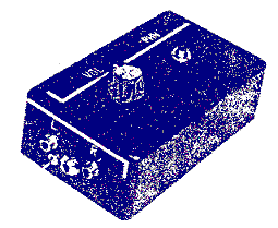
A steel enclosure will provide the best shielding; however, I installed a dozen headphone amps in bakelite project boxes, as shown at the beginning of this article, with good results. Aesthetics aside, bakelite boxes offer several advantages: you dont have to paint them; theyre fairly impervious to the occasional spilled beverage; and if they get dirty, you can just wipe them off. I had the ID plates (VOL, PHN, L, R) made at a local shop that engraves name tags, and glued them on with Scotch 6004 Super Strength Adhesive. This method of labeling is much more durable than using rub-on letters covered with a lacquer finish.
Since the RCA jacks mount through the case front, they have to be wired in place. With this type of enclosure, its easiest to attach the leads to the board first. then solder to the jacks, with the board not yet mounted. RCA jacks have a tendency to work loose; to secure them, squirt some silicone sealer around the jack-nuts.
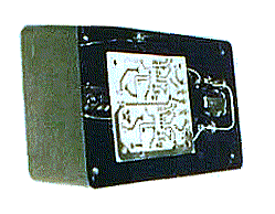
Figure 4 - Interior view of headphone amp enclosure.
On this particular unit, I added the mono switch and a quarter-inch input for guitar. I used a mini phone jack for a DC power input, mounted on the side of the case. In this case, the negative DC from the jack lead (or ground connection) should connect directly to the headphone jack ground. You could easily install a battery holder inside the case, instead, and add an on/off switch or a switching jack. A 9-volt rectangular battery will work, though four "AA" cells, at 6 volts, last much longer. The headphone amp works fine with +5 to +12 volts; standby current is only 4 mA. To simplify board-mounting, I used some fairly stiff, bare, 18-gauge thermostat wire and suspended the board below the headphone jack, as shown in Fig. 4 (dont try this with a mini headphone jack). With this mounting method, solder the wires to the jack first, then install it. Trim the leads approximately and test-mount the board before soldering.
If you prefer bracket mounting, you can drill mounting holes at one or more of the board corners, as indicated. Two of the holes pass through the board ground plane, connecting it to the chassis. With a metal enclosure, this simplifies wiring the jacks and negative DC lead, as the chassis becomes a ground plane. (If this causes a ground loop in your unit, insulate the board ground from the mounting bolt with a non-conductive washer and run discrete ground leads to the board.)
TESTING l-2-3
Doublecheck your wiring. If youre satisfied that all is well, set the volume control at about the ten oclock position, plug in your headphones and audio source, and power up. You should hear clean, clear reproduction. If not, power down and recheck your work.
Caution: This circuit can drive headphones to high sound-pressure levels that may damage hearing. Never use headphones at excessive volume levels. The reserve power can be safely used to drive a second pair of headphones, via a headphone Y-cable (Radio Shack catalog number 42-2448 or equivalent).
MODS
When configured for line-input operation, this headphone amp will work with most mixers, tape decks, tuners, CD players, etc. However, turntables with conventional moving-magnet cartridges require a phono preamp with the proper input load and RIAA equalization curve.
If you dont need stereo operation, delete the components for one of the channels, yielding a "one-chip" project. Connect the output of the remaining channel to both the tip and ring of the headphone jack by running a jumper wire between them.
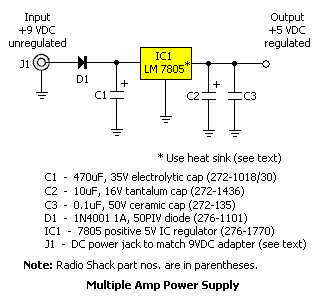
Figure 5
For studio monitoring applications, several headphone amps can be mounted together in a rack enclosure. Fig. 5 shows a regulated power supply, using common components, that will drive multiple amps. The circuitry is easily wired on a perf board or even point-to-point on terminal strips. Without a heat sink, the IC voltage regulator can handle one or two stereo headphone amps; with a clip-on heatsink, up to five; and with a heavy-duty, chassis-mount heat sink, up to 25, depending upon the impedance of the headphones used and the output power levels required. Double this capacity for mono amps. Note that to get this kind of power output, you'll have to use a hefty adapter, rated for at least 1 amp, such as the Radio Shack 277-1026.
The LM386 is a versatile, easily applied chip that's also useful for line, servo, and ultrasonic drivers; intercoms; TV sound amps; and power oscillators. See National Semiconductor's Linear Data Book for further applications.
In the meantime, if you, too, have a Stradivarius taste on a kazoo budget, this little headphone amp just might salvage your sonic sensibilities until you can afford that state-of-the-art power amp and studio monitors.
Addendum
8/14/98: The original schematic (figure 2) had the C5/C6 labels reversed. Also, the headphone jack wiring was reversed. The schematic has been updated.
c. 1989, Electronic Musician..
From Electronic Musician, March 1989, p. 68. (Republished with permission.)